Moment of inertia
This article is about the moment of inertia of a rotating object, also termed the mass moment of inertia. For the moment of inertia dealing with the bending of a beam, also termed the area moment of inertia, see second moment of area.
In classical mechanics, moment of inertia is also called mass moment of inertia, rotational inertia, polar moment of inertia of mass, or the angular mass, (SI units kg·m², US units lbm ft²). It is a property of a distribution of mass in space that measures its resistance to rotational acceleration about an axis. Newton's first law, which describes the inertia of a body in linear motion, can be extended to the inertia of a body rotating about an axis using the moment of inertia. That is, an object that is rotating at constant angular velocity will remain rotating unless acted upon by an external torque. In this way, the moment of inertia plays the same role in rotational dynamics as mass does in linear dynamics, describing the relationship between angular momentum and angular velocity, torque and angular acceleration. The symbols I and sometimes J are usually used to refer to the moment of inertia or polar moment of inertia.The moment of the inertia force on a particle around an axis multiplies the mass of the particle by the square of its distance to the axis, and forms a parameter called the moment of inertia. The moments of inertia of individual particles sum to define the moment of inertia of a body rotating about an axis. For rigid bodies moving in a plane, such as a compound pendulum, the moment of inertia is a scalar, but for movement in three dimensions, such as a spinning top, the moment of inertia becomes a matrix, also called a tensor.
In 1673 Christiaan Huygens derived the equation for the center of oscillation and oscillation period of compound pendulums, thus making use of the general equation for the moment of inertia for the first time. The term moment of inertia was introduced by Leonhard Euler in his book Theoria motus corporum solidorum seu rigidorum in 1765. In this book, he discussed the moment of inertia and many related concepts, such as the principal axis of inertia.
Overview
The moment of inertia of an object is defined by the distribution of mass around an axis. It depends not only on the total mass of the object, but also on the square of the perpendicular distance from the axis to each each element of mass. This means the moment of inertia increases rapidly as masses are distributed more distant from the axis. For example, consider two wheels that have the same mass, one that is the size of a bicycle wheel and one that is half that size. The larger wheel has four times the moment of inertia even though it is only twice the diameter.
Moment of inertia around a fixed axis is a scalar, however the rotation of a body in space can occur around the three coordinate axes. In this case, the moments of inertia associated with the three coordinate axes define a matrix of scalars called the inertia matrix, also known as the inertia tensor.
Scalar moment of inertia of a simple pendulum
 |
| Add caption |
This weight also generates a torque T on the pendulum around the pivot point and the acceleration of the mass a=rα is defined by the angular acceleration α of the pendulum, therefore

Add caption
In the same way, the kinetic energy of the pendulum mass is defined by its velocity v=rω using the angular velocity ω of the pendulum to yield

Add caption

Add caption
Scalar moment of inertia of a rigid body
Consider a rigid body rotating with angular velocity ω around a certain axis. The body consists of N point masses mi whose distances to the axis of rotation are denoted ri. Each point mass will have the speed vi = ωri, so that the total kinetic energy T of the body can be calculated as
Add caption

Similarly, the moment of inertia of a continuous solid body rotating about a known axis can be calculated by replacing the summation with the integral:

Moment of inertia theorems
Calculations for the moment of inertia (MOI) of a body are not easy in general. The process can be simplified in the following ways:- Choosing axes to take advantage of geometric symmetries
- Physical homogeneity (i.e., uniform mass distribution) making the density function ρ(r) become constant (elementary calculations, or generally an approximation)
- Use of the following theorems see below for details:
| Theorem | Nomenclature | Equation |
|---|---|---|
| Superposition Principle for Moment Of Inertia (MOI) about any chosen Axis |
Inet = resultant MOI (about any one axis) |  |
| Parallel axis theorem | M = total mass of body d = perpendicular distance from an axis through the Center Of Mass (COM) to another parallel axis ICOM = MOI about the axis through the COM Id = MOI about the parallel axis |
 |
| Perpendicular axis theorem | i, j, k refer to MOI about any three mutually perpendicular axes. The sum of MOI about any two is greater than or equal to the third. |
 |
Properties
SuperpositionThe moment of inertia of the body is additive. That is, if a body can be decomposed (either physically or conceptually) into several constituent parts, then the moment of inertia of the whole body about a given axis is equal to the sum of moments of inertia of each part around the same axis.
Basing just on the dimensional analysis, the moment of inertia must take the form I = c·M·L2, where M is the mass, L is the “size” of the body in the direction perpendicular to the axis of rotation, and c is a dimensionless inertial constant. Additionally, the length
 is called the radius of gyration of the body.
Perpendicular Axes
If Ix, Iy, Iz are moments of inertia around three perpendicular axes passing through the body’s center of mass, then each of them cannot be greater than the sum of two others: for example Iz ≤ Ix + Iy. Here the equality holds only if the body is flat and located in the Oxy coordinate plane.
Parallel Axes
If the object’s moment of inertia ICOM around a certain axis passing through the center of mass is known, then the parallel axis theorem or Huygens–Steiner theorem provides a convenient formula to compute the moment of inertia Id of the same body around a different axis, which is parallel to the original and located at a distance d from it. The formula is only suitable when the initial and final axes are parallel. In order to compute the moment of inertia about an arbitrary axis, one has to use the object’s moment of inertia tensor.
Examples
Main article: List of moments of inertia
| Add caption |
The easiest way to calculate this molecule’s moment of inertia is to use the parallel axis theorem. If we consider rotation around the axis passing through the atom m1, then the moment of inertia will be I1 = m1·0 + m2·d 2 = m2d 2. On the other hand, by the parallel axis theorem this moment is equal to I1 = I + (m1 + m2)·a 2, where I is the moment of inertia around the axis passing through the center of mass, and a is the distance between the center of mass and the first atom. By the center of mass formula, this distance is equal to a = m2 d / (m1 + m2). Thus,

Let Oz be the axis of rotation, and Ox the axis along the rod. If ρ is the density, and s the cross-section of the rod (so that m = ρℓs), then the volume element for the integral formula will be equal to dV = s·dx, where x changes from −½ℓ to ½ℓ. The moment of inertia can be found by computing the integral:


Suppose Oz is the axis of rotation. The distance from point r = (x, y, z) towards the axis Oz is equal to d(r)2 = x 2 + y 2. Thus, in order to compute the moment of inertia Iz, we need to evaluate the integral ∭(x 2 + y 2) dV. The calculation considerably simplifies if we notice that by symmetry of the problem, the moments of inertia around all axes are equal: Ix = Iy = Iz. Then


When considering mechanisms like gear trains, worm and wheel, where there are more than one rotating element, more than one axis of rotation, an equivalent moment of inertia for the system should be found. Practically when a geared system is enclosed, equivalent moment of inertia can be measured by measuring the angular acceleration for a known torque or theoretically it can be estimated when the masses and dimensions of the rotating elements and shafts are known. In this practical the equivalent moment of inertia of a worm and wheel system is measured using above mention methods.
Polar moment of inertia
If a mechanical system is constrained to move parallel to a fixed plane, then the rotation of a body in the system occurs around an axis k perpendicular to this plane. In this case, the moment of inertia of the mass in this system is a scalar known as the polar moment of inertia. The definition of the polar moment of inertia can be obtained by considering momentum, kinetic energy and Newton's laws for the planar movement of a rigid system of particles.If a system of n particles, Pi, i=1,...,n, are assembled into a rigid body, then the momentum of the system can be written in terms of position and velocity relative to a reference point R,

For planar movement the angular velocity vector is directed along the unit vector k which is perpendicular to the plane of movement. Introduce the unit vectors ei from the reference point R to a point ri, and the unit vector ti=kxei so

Angular momentum in planar movement
The angular momentum vector for the planar movement of a rigid system of particles is given by

For a given amount of angular momentum, a decrease in the moment of inertia results in an increase in the angular velocity. Figure skaters can change their moment of inertia by pulling in their arms. Thus, the angular velocity achieved by a skater with outstretched arms results in a greater angular velocity when the arms are pulled in, because of the reduced moment of inertia.
Kinetic energy in planar movement
 |
| Add caption |


Newton's laws for planar movement

The kinematics of a rigid body yields the formula for the acceleration of the particle Pi in terms of the position R and acceleration A of the reference particle as well as the angular velocity vector ω and angular acceleration vector α of the rigid system of particles as,


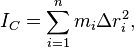
Use the center of mass C as the reference point and define the moment of inertia relative to the center of mass IC, then the equation for the resultant torque simplifies to

Moment of inertia matrix
The scalar moments of inertia appear as elements in a matrix when a system of particles is assembled into a rigid body that moves in three dimensional space. This inertia matrix appears in the calculation of the angular momentum, kinetic energy and resultant torque of the rigid system of particles. Let the system of particles Pi, i=1,...,n be located at the coordinates ri and velocities vi. Select a reference point R and compute the relative position and velocity vectors,Angular momentum
The angular momentum of a rigid system of particles measured relative to the center of mass R is
In order to use this formula for angular momentum to obtain the matrix of mass moment of inertias, also called the inertia matrix, introduce the skew-symmetric matrix [B] constructed from a vector b that performs the cross product operation, such that
![[B]\mathbf{y} =\mathbf{b}\times\mathbf{y}.](http://upload.wikimedia.org/math/4/d/1/4d1b1c730078685ef0304ea98955e7f0.png)
![[B] = \begin{bmatrix} 0 & -b_z & b_y \\ b_z & 0 & -b_x \\ -b_y & b_x & 0 \end{bmatrix}.](http://upload.wikimedia.org/math/7/e/0/7e0cd9bfa455706eb7ee49f5e55db18a.png)
![\mathbf{L} = (-\sum_{i=1}^n m_i [r_i-R][r_i-R])\omega = [I_R]\omega,](http://upload.wikimedia.org/math/8/7/c/87ca710e6df69593b2cad90f8a028ee0.png)
![[I_R] = -\sum_{i=1}^n m_i[r_i-R][r_i-R],](http://upload.wikimedia.org/math/6/1/7/6172da6c296d5b68698800c3818e991b.png)
Kinetic energy
The kinetic energy of a rigid system of particles can be formulated in terms of the center of mass and a matrix of mass moments of inertia of the system. Let the system of particles Pi, i=1,...,n be located at the coordinates ri and velocities vi, then the kinetic energy is

![T=\frac{1}{2}\omega\cdot(- \sum_{i=1}^n m_i [r_i - C][r_i - C]) \omega + \frac{1}{2}(\sum_{i=1}^n m_i) \mathbf{V}\cdot\mathbf{V}.](http://upload.wikimedia.org/math/1/1/f/11f1e62bbd5d0bdd7a6d78d019592f59.png)
![T=\frac{1}{2}\omega\cdot[I_C]\omega +\frac{1}{2}M\mathbf{V}\cdot\mathbf{V}.](http://upload.wikimedia.org/math/c/1/0/c10d2b2633417f0b9498fd85b6965aab.png)
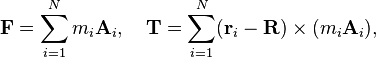
Resultant torque
The inertia matrix appears in the application of Newton's second law to a rigid assembly of particles. The resultant torque on this system is,

![\mathbf{T} =( -\sum_{i=1}^n m_i[r_i-C][r_i-C])\times\alpha + \omega\times(- \sum_{i=1}^n m_i [r_i-C][r_i-C])\omega.](http://upload.wikimedia.org/math/4/e/a/4ea889378e88290677cf5be6fcbbdc48.png)

Thus, the resultant torque on the rigid system of particles is given by
![\mathbf{T} =[I_C]\alpha + \omega\times[I_C]\omega,](http://upload.wikimedia.org/math/2/6/4/264a80b76f9c7b43c81b1ab985fa9d0d.png)
Parallel axis theorem
The inertia matrix of a rigid system of particles depends on the choice of the reference point. There is a useful relationship between the inertia matrix relative to the center of mass C and the inertia matrix relative to another point R. This relationship is called the parallel axis theorem.Consider the inertia matrix [IR] obtained for a rigid system of particles measured relative to a reference point R, given by
![[I_R] = -\sum_{i=1}^n m_i[r_i-R][r_i-R].](http://upload.wikimedia.org/math/2/d/a/2da016aba839cd174e870b60450c4095.png)

![[I_R] = -\sum_{i=1}^n m_i[r_i - C - d][r_i - C - d].](http://upload.wikimedia.org/math/f/b/8/fb8e097fe597d69cebdabc94f738399a.png)
![[I_R] = (-\sum_{i=1}^n m_i [r_i - C][r_i - C]) + (\sum_{i=1}^n m_i[r_i - C])[d] + [d](\sum_{i=1}^n m_i[r_i - C]) + (-\sum_{i=1}^n m_i)[d][d].](http://upload.wikimedia.org/math/2/d/1/2d171c02695341cd91c27a9379c2c50d.png)
The result is the parallel axis theorem,
![[I_R] = [I_C] - M[d]^2,](http://upload.wikimedia.org/math/e/a/c/eacf10db9256a59b409bbc8588e86b02.png)
Moment of inertia around an arbitrary axis
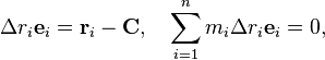
The moment of inertia of a body around an arbitrary axis in space is a scalar that is computed as the sum of the distance squared from the axis to each of the mass elements. This scalar can be computed from the moment inertia matrix of the body using the unit vector along the axis.Let a rigid assembly of rigid system of N particles, Pi, i=1,...,N, have coordinates ri. Choose R as a reference point and compute the moment of inertia around an axis L defined by the unit vector S through the reference point R. The moment of inertia of the system around this line L=R+tS is computed by determining the perpendicular vector from this axis to the particle Pi given by
![\Delta\mathbf{r}_i = (\mathbf{r}_i-\mathbf{R}) - (\mathbf{S}\cdot(\mathbf{r}_i-\mathbf{R}))\mathbf{S} = [[I]-[\mathbf{S}\mathbf{S}^T]](\mathbf{r}_i-\mathbf{R}),](http://upload.wikimedia.org/math/a/e/d/aedec545149d90af3fb4f450d08f07a5.png)
Introduce the skew-symmetric matrix [S] such that [S]y=S x y, then we have the identity
![-[S]^2 = [I]-[\mathbf{S}\mathbf{S}^T],](http://upload.wikimedia.org/math/d/7/5/d754566c8ed6ca11f079e927cf398153.png)
The magnitude squared of the perpendicular vector is
![|\Delta\mathbf{r}_i|^2 = (-[S]^2(\mathbf{r}_i-\mathbf{R})) \cdot (-[S]^2(\mathbf{r}_i-\mathbf{R})) = -\mathbf{S}\cdot[r_i-R][r_i-R]\mathbf{S}.](http://upload.wikimedia.org/math/8/1/2/81281b741a1cecfb78d0a9c1a7cb9c27.png)

![-(\mathbf{r}_i-\mathbf{R})\times\mathbf{S}\cdot(\mathbf{S}\times(\mathbf{r}_i-\mathbf{R})=-\mathbf{S}\cdot[r_i-R][r_i-R]\mathbf{S},](http://upload.wikimedia.org/math/2/1/9/219b8e798f8c89911108d5df8dd88e7b.png)
Thus, the moment of inertia around the line L through R in the direction S is given by the scalar
![I_L = \sum_{i=1}^N m_i |\Delta\mathbf{r}_i|^2= -\sum_{i=1}^N m_i \mathbf{S}\cdot[r_i-R][r_i-R]\mathbf{S},](http://upload.wikimedia.org/math/c/4/5/c4545ea25135925232401cef52ef75be.png)
![I_L = \mathbf{S}\cdot(-\sum_{i=1}^N m_i [r_i-R][r_i-R])\mathbf{S}=\mathbf{S}\cdot[I_R]\mathbf{S},](http://upload.wikimedia.org/math/7/6/f/76f0767c2ecb3c1db1ea48687bab7af0.png)
Moment of inertia tensor
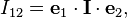
The moment of inertia for a rigid body moving in space is a tensor formed from the scalars obtained from the moments of inertia and products of inertia about the three coordinate axes. The moment of inertia tensor is constructed from the nine component tensors,

For a rigid system of particles Pk, k=1,...,N each of mass mk with position coordinates rk=(xk, yk, zk), the inertia tensor is given by
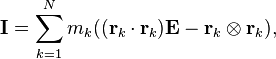

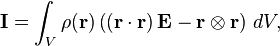
The inertia tensor defines the moment of inertia about an arbitrary axis defined by the unit vector n as the product,

The components of tensors of degree two can be assembled into a matrix. For the inertia tensor this matrix is given by,
![[I] = \begin{bmatrix}
I_{11} & I_{12} & I_{13} \\
I_{21} & I_{22} & I_{23} \\
I_{31} & I_{32} & I_{33}
\end{bmatrix}=\begin{bmatrix}
I_{xx} & I_{xy} & I_{xz} \\
I_{xy} & I_{yy} & I_{yz} \\
I_{xz} & I_{yz} & I_{zz}
\end{bmatrix}.](http://upload.wikimedia.org/math/2/f/4/2f45001a4bbd9decca149d467e37f1bd.png)
Moment of inertia reference frames
The use of the inertia matrix in Newton's second law assumes its components are computed relative to axes parallel to the inertial frame and not relative to a body-fixed reference frame. This means that as the body moves the components of the inertia matrix change with time. In contrast, the components of the inertia matrix measured in a body-fixed frame are constant.Body frame inertia matrix
Let the body frame inertia matrix relative to the center of mass be denoted [ICB], and define the orientation of the body frame relative to the inertial frame by the rotation matrix [A], such that,![\mathbf{x}=[A]\mathbf{y},](http://upload.wikimedia.org/math/7/7/9/779d2e831aeb83dedcf578248aca0996.png)
![[I_C]=[A][I_C^B][A^T].](http://upload.wikimedia.org/math/1/c/c/1cc7758544fc41992d847e31ec89f2f0.png)
Principal axes
Measured in the body frame the inertia matrix is a constant real symmetric matrix. A real symmetric matrix has the eigendecomponsition into the product of a rotation matrix [Q] and a diagonal matrix [Λ], given by![[I_C^B]=[Q][\Lambda][Q^T],](http://upload.wikimedia.org/math/a/e/1/ae160e5338f44742db9862d584d99da9.png)
![[\Lambda]= \begin{bmatrix}
I_{1} & 0 & 0 \\
0 & I_{2} & 0 \\
0 & 0 & I_{3}
\end{bmatrix}.](http://upload.wikimedia.org/math/a/b/8/ab877429a794912f995958a1ca799f7c.png)
For bodies with constant density an axis of rotational symmetry is a principal axis.
Inertia ellipsoid

![\mathbf{x}^T[\Lambda]\mathbf{x}=1,](http://upload.wikimedia.org/math/0/9/5/09526865c0b3405374b3d0502985fa74.png)


![\mathbf{x}^T[\Lambda]\mathbf{x}=|\mathbf{x}|^2\mathbf{n}^T[\Lambda]\mathbf{n} = |\mathbf{x}|^2I_n = 1,](http://upload.wikimedia.org/math/5/3/a/53a7149fd1dcb464d29b299ed1d9260f.png)

Parallel axis theorem
It is useful to note here that if the moment of inertia matrix or tensor relative to the center of mass, then it can be determined relative to any other reference point in the body using the parallel axis theorem. If [ICB] is the moment of inertia matrix in the body frame relative to the center of mass C, then the moment of inertia matrix [IRB] in the same frame but relative to a different point R is given by![[I_R^B] = [I_C^B] - M[d]^2,](http://upload.wikimedia.org/math/3/2/2/322a461e73eb4969b072fdc872a9a688.png)
The tensor form of the parallel axis theorem is given by

Identities for a skew-symmetric matrix
In order to compare formulations of the inertia matrix in terms of a product of skew-symmetric matrices and in terms of a tensor formulation, the following identities are useful.Let [R] be the skew symmetric matrix associated with the position vector R=(x, y, z), then the product in the inertia matrix becomes
![-[R][R]= -\begin{bmatrix} 0 & -z & y \\ z & 0 & -x \\ -y & x & 0 \end{bmatrix}^2 = \begin{bmatrix}
y^2+z^2 & -xy & -xz \\ -y x & x^2+z^2 & -yz \\ -zx & -zy & x^2+y^2 \end{bmatrix}.](http://upload.wikimedia.org/math/2/6/f/26f0852e9f1cdba1713edef8025d3b08.png)
![-[R]^2 = |\mathbf{R}|^2[I] -[\mathbf{R}\mathbf{R}^T]=
\begin{bmatrix} x^2+y^2+z^2 & 0 & 0 \\ 0& x^2+y^2+z^2 & 0 \\0& 0& x^2+y^2+z^2 \end{bmatrix}- \begin{bmatrix}x^2 & xy & xz \\ yx & y^2 & yz \\ zx & zy & z^2\end{bmatrix},](http://upload.wikimedia.org/math/8/a/9/8a95843bc8744e7ad9c89ea74c6678f0.png)
Also notice, that
![|\mathbf{R}|^2 = \mathbf{R}\cdot\mathbf{R} =\operatorname{tr}[\mathbf{R}\mathbf{R}^T],](http://upload.wikimedia.org/math/7/1/a/71a3a6cbb513b8999a19118b6a4d8a68.png)
No comments:
Post a Comment